

Understand airflow, static pressure and operating points for better axial fan selection.
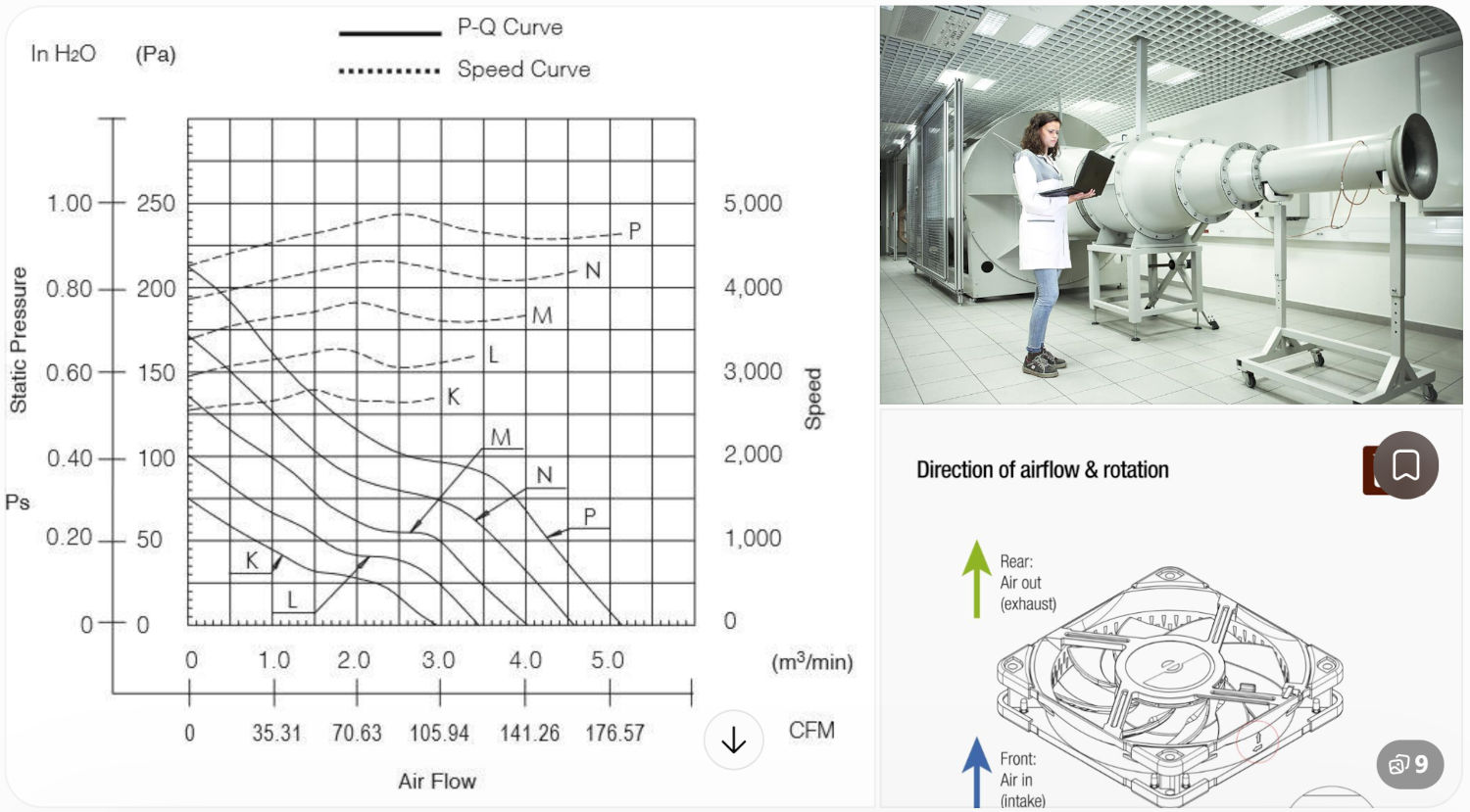
When selecting an axial cooling fan for electronic devices, industrial equipment or ventilation systems, airflow and noise are usually the first specifications to consider. However, choosing a fan based only on its maximum airflow rating may result in poor cooling performance in actual applications.
The P-Q curve (Pressure-Flow Curve) is one of the most important technical references for evaluating axial fan performance. It shows the relationship between airflow and static pressure, helping engineers understand how a fan performs under different system resistance conditions.
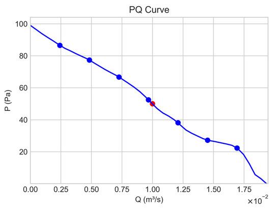
Airflow refers to the volume of air delivered by a fan per unit of time. Common units include:
On a P-Q curve, airflow is represented by the horizontal axis. Moving from left to right indicates increasing airflow.
Static pressure represents the pressure generated by a fan to overcome resistance in an air duct or ventilation system. Common units include:
Static pressure is represented by the vertical axis. Generally, the available static pressure decreases as airflow increases.
Maximum static pressure is the pressure generated when the fan outlet is completely blocked and airflow is zero. It is also known as shut-off pressure. This value indicates the pressure capability of a fan but does not represent its normal operating condition.
Maximum airflow is the highest airflow a fan can deliver under free-air conditions, where external system resistance is approximately zero. It is commonly used as a reference when comparing fan airflow capacity.
The operating point is the intersection of the fan performance curve and the system resistance curve. It determines the actual airflow and pressure delivered by the fan in a real application.
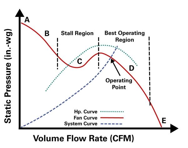
Important: For practical fan selection, the operating point is more important than either maximum airflow or maximum static pressure alone.
When a fan is installed inside equipment, air must pass through various components, such as filters, heat sinks, ventilation grilles, air ducts and internal electronic components. These components create airflow resistance.
The system resistance curve describes the pressure required to maintain different airflow rates. In many typical ventilation systems, pressure loss approximately follows the square of airflow:
P = K × Q²
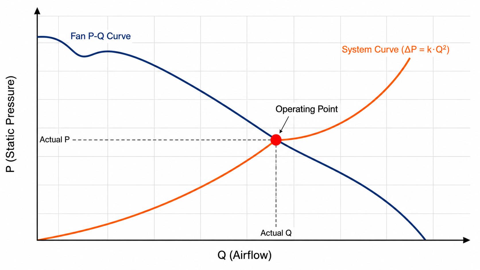
As airflow increases, system resistance also increases significantly. The intersection of the fan curve and system resistance curve determines the actual operating point.
Adding filters, grilles or other restrictions increases system resistance and reduces the actual airflow delivered by the fan.
Consider a cooling application with the following requirements:
Calculate the airflow needed to remove heat from the equipment based on its thermal requirements.
Consider pressure losses caused by filters, grilles, heat sinks and internal air passages.
Locate 80 m³/h on the airflow axis and check whether the fan can provide at least 35 Pa of static pressure at that airflow.
Confirm that the fan can achieve the required airflow and pressure under actual installation conditions.
The best fan is not necessarily the one with the highest maximum airflow. It is the one that provides suitable airflow and pressure under actual system resistance conditions.
A common mistake in cooling system design is assuming that a fan will deliver its rated maximum airflow after installation.
In reality, actual airflow is affected by several factors:
For example, an axial fan rated at 150 m³/h under free-air conditions may deliver considerably less airflow when installed inside a compact electronic enclosure.
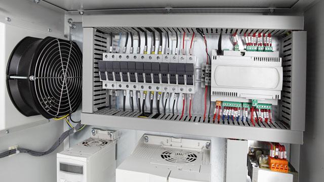
Different cooling applications require different airflow and static pressure characteristics.
Axial fans are particularly suitable for applications requiring high airflow with relatively low installation resistance. For systems with narrow air passages or high resistance, engineers should carefully evaluate whether an axial fan can provide sufficient static pressure. In some applications, a centrifugal blower may be a more suitable solution.
At Coolcom, we understand that selecting a cooling fan involves more than simply matching its dimensions and rated airflow.
We provide customized axial fan solutions based on different equipment requirements.
Our engineering team can help evaluate:
Whether you are developing electronic equipment, industrial control systems or smart devices, Coolcom can help you identify a suitable cooling fan solution.
The P-Q curve is an essential tool for understanding axial fan performance.
By learning how to identify maximum airflow, maximum static pressure and the actual operating point, engineers can make more informed fan selection decisions.
The most important parameter is not the maximum airflow printed on the datasheet, but the airflow the fan can deliver under your actual system resistance.
Need help selecting an axial cooling fan? Contact Coolcom with your equipment dimensions, required airflow and operating conditions. Our engineering team will help you find the right cooling solution.


